Logic Node Examples
Example Logic Crafting Programs
This is a curated set of useful Logic Nodes. Read through the examples to see how Logic Crafting works and how it can be used for a variety of tasks. For full documentation on what each block does, visit the Logic Blocks page.
Start and Stop
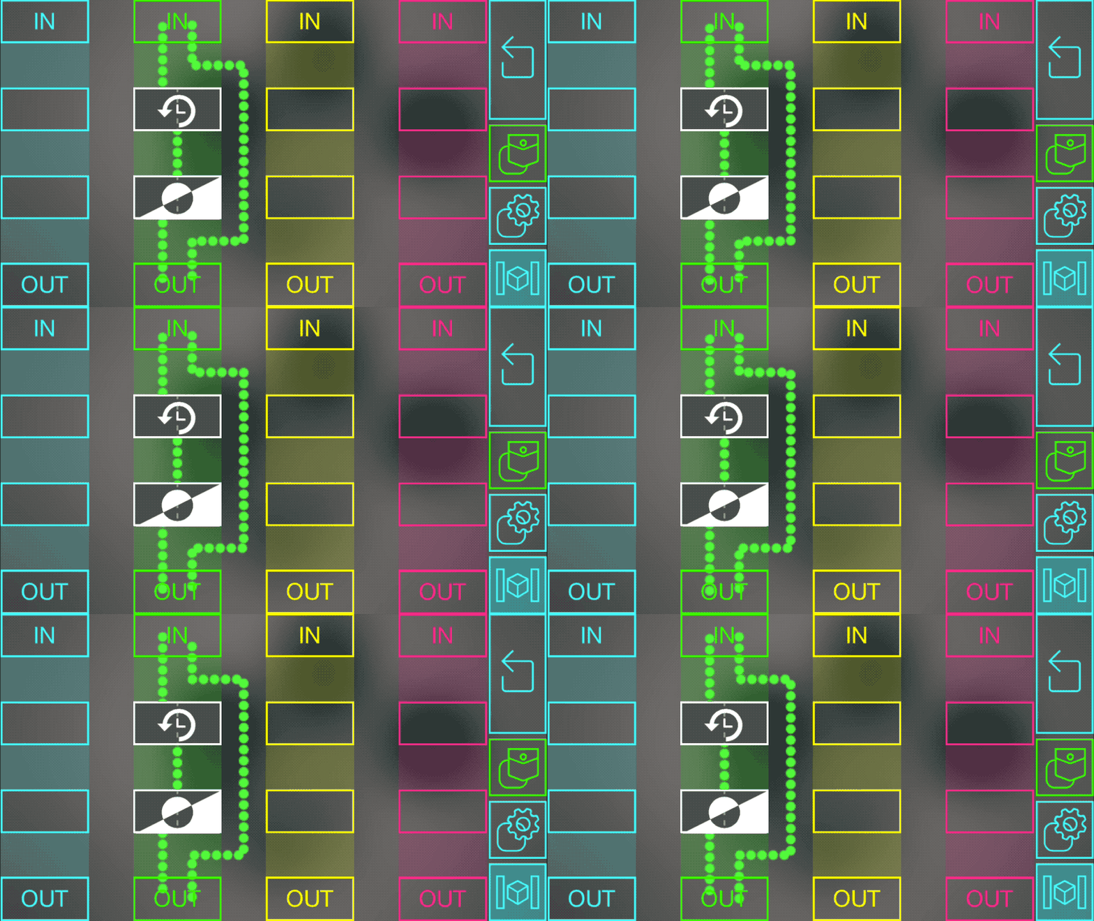
This program uses a delay block and an inverter to trigger an action, and then stop it a few seconds later.
Imagine that you connect the green input to a button and the green output to a light. When you pressed the button, a 1 arrives in the green input and immediately turns the light on because of the link from green IN to green OUT. But it also sends a 1 to the delay block, which will wait a few seconds and then send the 1 to the inverter block. This changes the 1 to a 0 and sends it to green OUT, which turns the light back off.
The amount of time the light stays on can be changed by tapping on the delay block and choosing a number of seconds.
Delay Chain
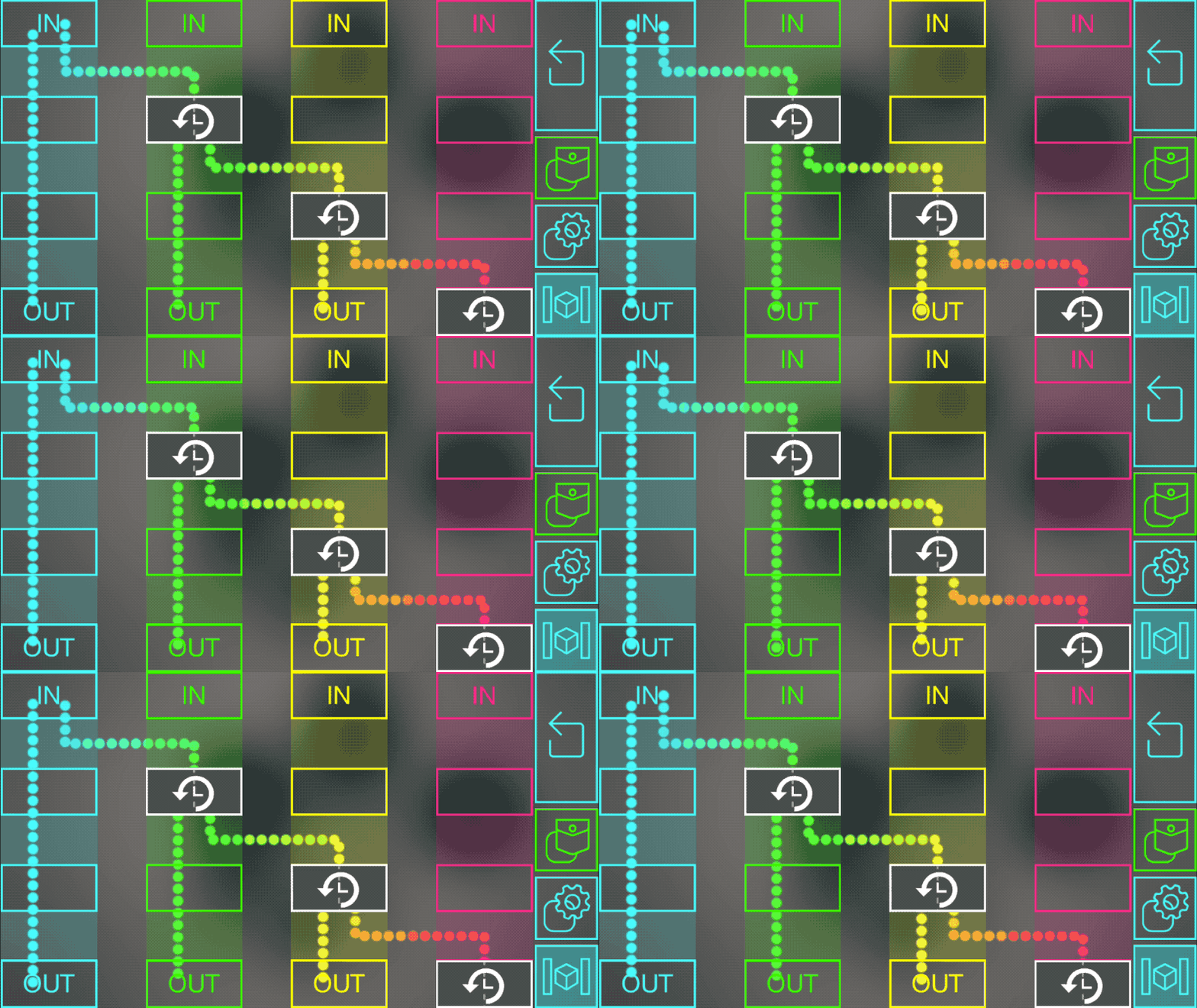
This program lets a single action trigger a sequence of events with delays in between each one.
Imagine you connect a button to the blue input, and lights to each of the outputs. This will immediately turn on the first light (because of the direct link from blue IN to blue OUT. It also trigger the delay in the green column, which will wait a second before activating the light connected to green OUT. It triggers the yellow delay block, which does the same for the red, eventually turning on all the lights.
Math
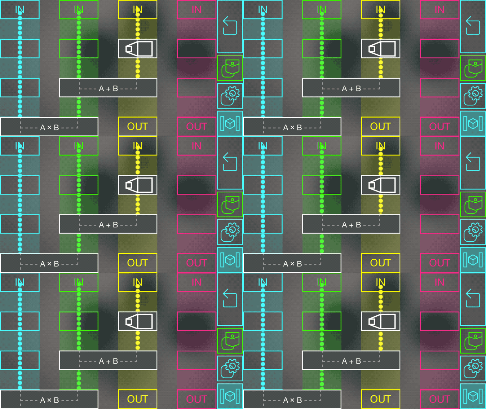
There are a few blocks to perform different math operations on incoming values. This program uses a scale, add, and multiply block to compute the value sent to blue OUT. As an example, imagine the blue, green, and yellow inputs are connected to distance sensors, the blue output is connected to a light, and the scale block has a scale factor of 3 (you can change this by tapping on the block).
In this case, the blocks compute the function: Blue OUT = Blue IN x (Green IN + (3 x Yellow IN))
If Both Are On...
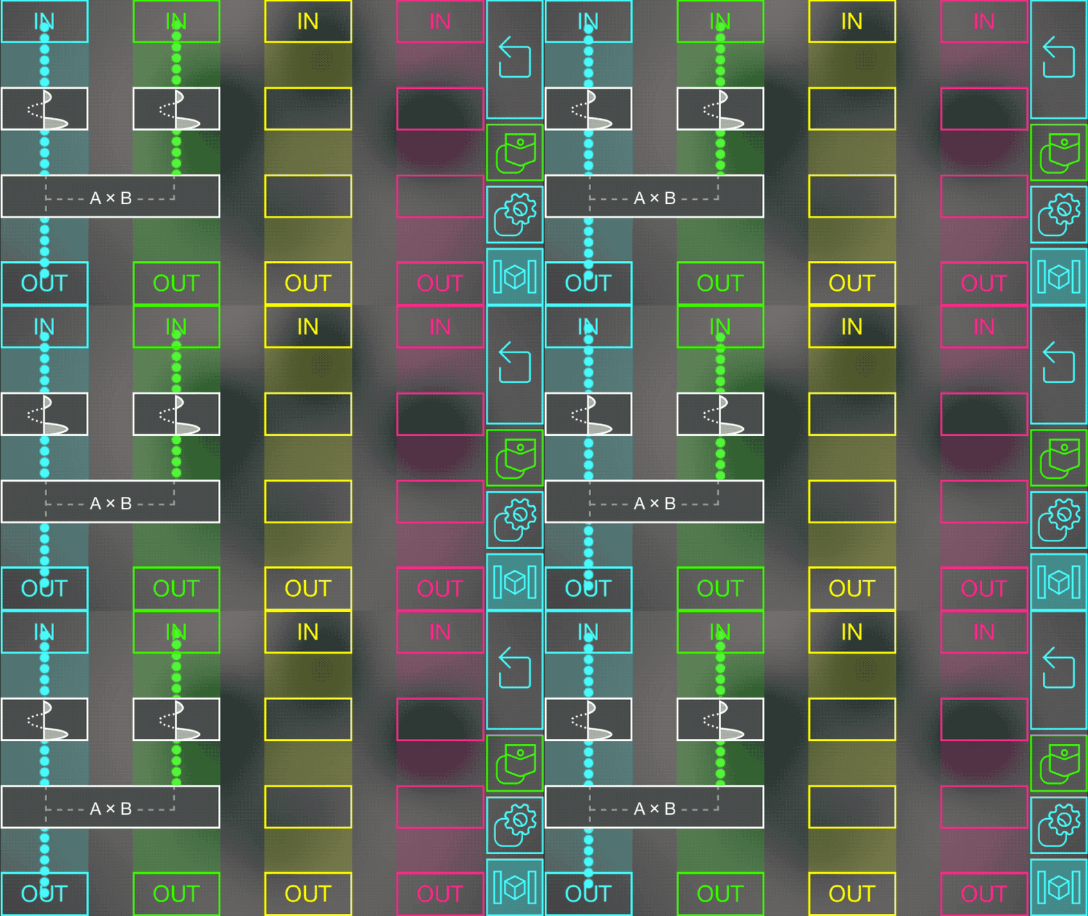
This program is useful in a lot of situations where you want to know if two objects are both “on” (meaning they have values of 1, or at least something above a certain threshold). You connect one object to the blue input, the other to the green input, and the blue output will give you a 1 if they are both on, or a 0 otherwise.
This works by sending each object’s data through a threshold block set to “digital” mode in the settings. These will output a 1 if the data is above 0.5 (or whatever threshold chosen in the settings), or a 0 otherwise. The two results are then multiplied. If either object value was less than the threshold, this will multiply the other value by 0 so the result sent to blue OUT will also be a 0. The only time it won’t get set to 0 is if both values were above their thresholds.
If Either Are On...
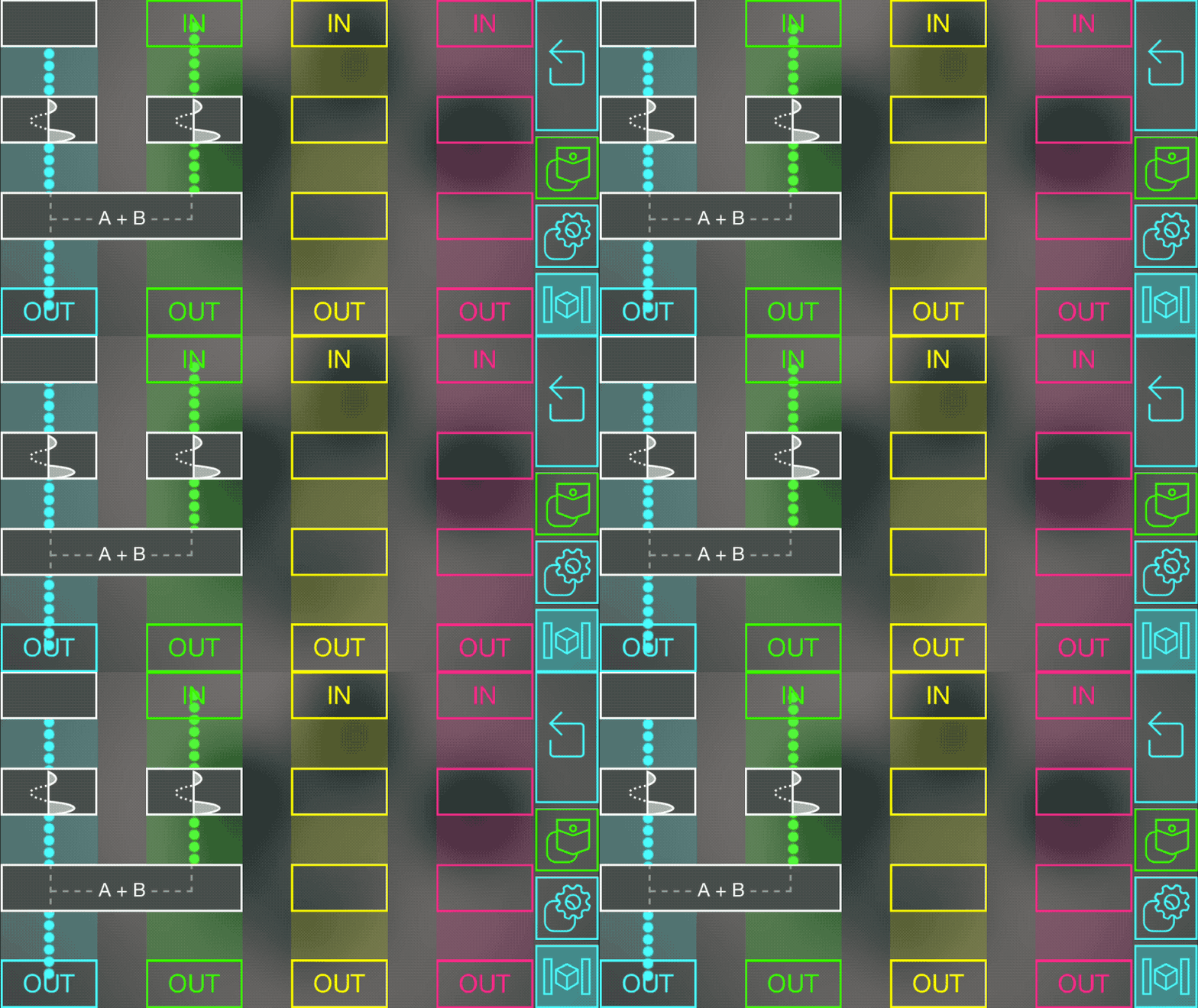
This program works almost exactly as the “If Both Are On…” example above. The only difference is that we use an add block instead of a multiply block.
Remember that the inputs to the add block will either be 0 (if that object is off) or 1 (if that object is on) because of the threshold blocks. If we add them together, the only time the sum will be 0 is when both objects are off. Otherwise, the sum will be 1 (if only one of them is on) or 2 (if both are on). The block keeps the output within the range of 0 to 1 so it will actually be 1 even if both are on.
An example use for this would be to connect two lights to the inputs, and a radio to the output. This would make the radio play when either light is on, but when they are both off it would stop playing.
Rotating Car
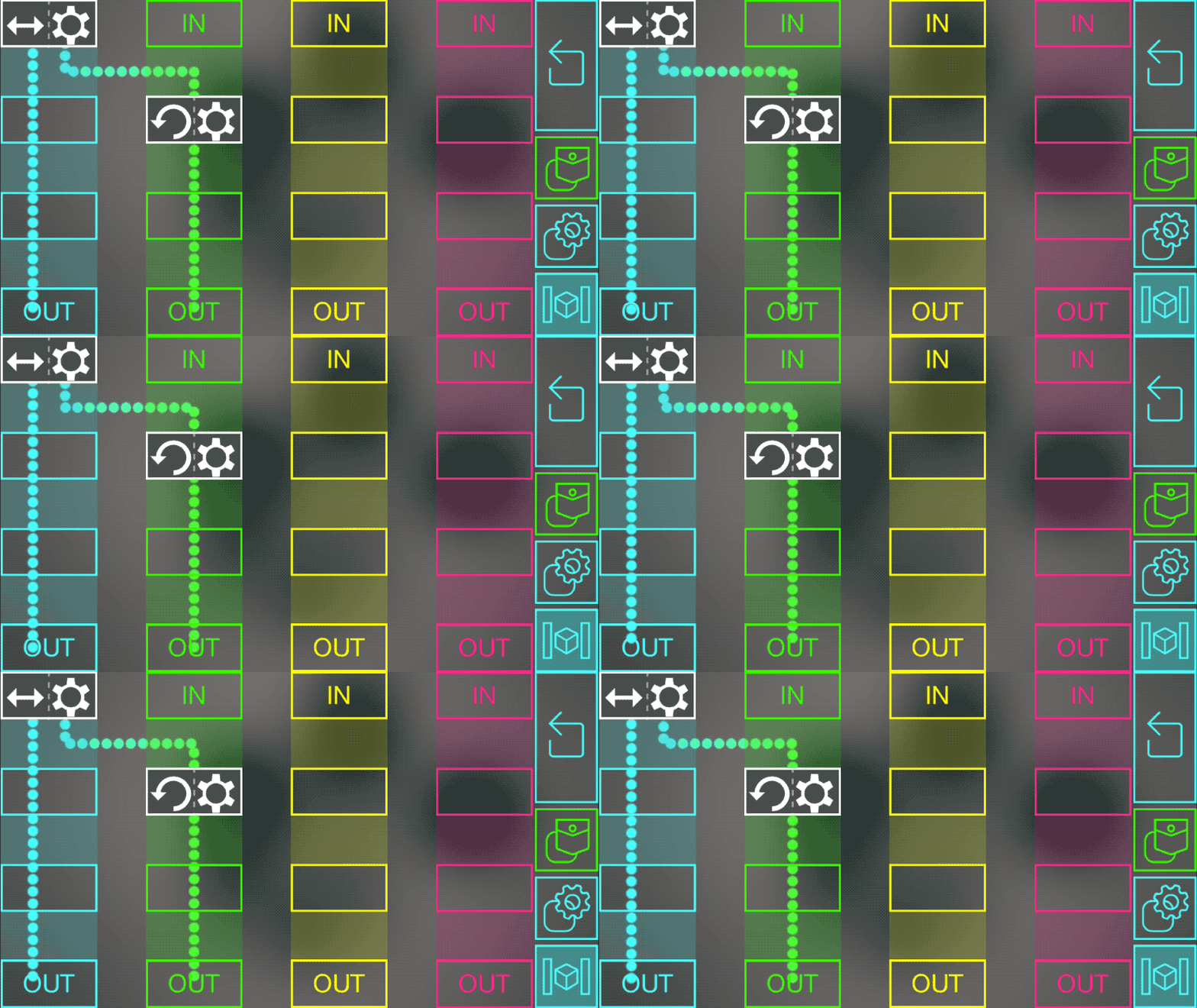
In this example, imagine you built a Lego car or robot with two wheels. If they both rotate forwards, the car will drive forwards. If they both rotate backwards, the car will drive backwards. But if they spin in opposite directions, the car will turn.
This program lets you use a sensor to control how fast your car will spin. Connect the sensor to the logic node’s blue input, and connect one motor to the blue output and the other to the green output.
The Full Range block connected to blue IN takes the sensor values, which range from 0 to 1, and converts them to the range of -1 to 1 so that it can make the motors spin forwards or backwards.
Let’s say the sensor is fully on, so it has a value of 1. The link to blue OUT will make that motor spin forwards at full speed. The other link goes through an Invert Motor block, which outputs -1, and makes the motor connected to green OUT spring backwards at full speed.
As the sensor value gets smaller, the car spinning will slow down, and eventually start spinning in the other direction.
Engine On/Off Switch
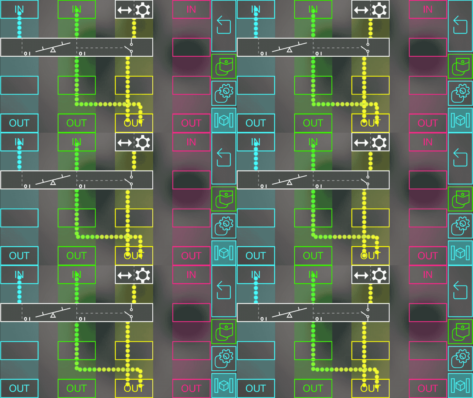
This program uses a seesaw block to allow or stop the data flowing from yellow IN to yellow OUT.
Imagine yellow OUT is connected to a Lego car’s wheels, yellow IN is connected to a controller that lets you set the speed, and blue IN and green IN are connected to buttons.
Pressing the green button once will “turn on the engine” by allowing data to flow into the motor from the Full Range block. While it is on, you can control the speed of the motor with the controller connected to the yellow input. You can “turn off the engine” by pressing the blue button once. This toggles off the seesaw block, which stops new speed values from going through the yellow column.
There is also a link from the green column to yellow OUT. This actually stops the car motor when you press the blue button, by sending a 0 to the motor. If we didn’t include this, turning off the car would only stop you from changing its speed with the controller, but it might already be moving.
